Project overview
Project details
- Client
- International EPC contractor (petrochemical)
- Year
- 2026
- Category
- Firefighting
- Location
- Ras Laffan Industrial City
- HDPE
- ASME B31.3
- AWWA M55
- ISO 4427-1
- API 15LE
- CAESAR II
- Crane Crossing
- Surge Analysis
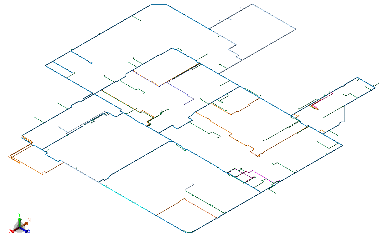
Design and stress analysis of a plant-wide buried HDPE firewater network at Ras Laffan Industrial City, ranging from DN 630 to DN 63. The scope covers pressure containment, soil-pipe interaction, crane crossings, upheaval buckling, seismic, surge and thrust-block loads.
- DN 630–63pipe sizes in one network
- 20crane crossings assessed
- 73%surge, governing occasional case
The challenge
- The network is PE 100 polyethylene and spans ten diameters.
- Cover varied from shallow trafficked crossings to deep backfill, with groundwater 1.5 m below grade.
- As a flexible pipe, its performance depends on soil-pipe interaction, and its modulus drops steeply with temperature and load duration.
- Five separate assessments were needed, each covering a different failure mode and staying consistent with the others.
- Construction required 1,600 t and 2,500 t class crawler cranes to travel and stand over the network at ten locations each.
- A separate hydraulic transient study returned unbalanced thrust at direction changes about an order of magnitude above the operating case.
Our approach
- Pressure containment. Every line was sized against maximum design stress per ISO 4427-1, confirming adequate margin for the selected SDR series.
- External loading. Assessed to AWWA M55 across the cover envelope. Shallow cases were checked under live load and deep cases under dead load, with buoyancy reduction applied below the water table.
- Upheaval stability. Assessed with the Peters method, comparing thermal-expansion restraining force against soil uplift resistance. The result was converted into a maximum allowable overbend angle for construction.
- Crane crossing. Two cranes were assessed: a 72 m Terex Demag CC2500-1 and a 114 m Sany SCE 16000A with 340 t combined counterweight. Track pressures were applied at ten crossings per crane, at cover depths from 504 mm to just over 3 m. The full track load was placed on a single wheel, a deliberately conservative live-load case.
- Stress analysis. The network was modelled in CAESAR II 2019 with soil restraints from site geotechnical data and analysed to ASME B31.3 for hydrotest, sustained, operating, expansion and occasional cases at two burial depths. Surge thrust forces came from a separate study and were applied at the highest-demand elbows, then combined with the sustained case as the governing occasional condition. A parallel run with soil friction suppressed produced the friction-free reaction loads given to civil for thrust block design.
The outcome
- Ring deflection. Under 3.2% for SDR 9 (4% allowable) and under 2.4% for SDR 13.6 (6% allowable). Constrained buckling and vacuum resistance passed at the shallowest cover, and hoop compressive stress at the deepest cover was an order of magnitude below the PE 100 allowable.
- Upheaval. Large margins for all sizes. The maximum allowable overbend angle exceeded the elastic bend radius for every diameter, so the pipe could follow the natural site profile.
- Crane clearance. Both cranes were cleared to travel and stand over the network without protection slabs, load-spreading mats or trench re-profiling. Peak deflection under the heavier crane was 3.95% against the 4% allowable at the shallowest crossing, the tightest margin on the project, obtained under the single-wheel idealisation.
- Restriction. Outriggers may not be set directly above a pipe. This was issued as a lift-plan constraint for construction, not a design change.
- Stress results. All code cases passed at both burial depths. Surge was the only governing condition, at 73% of the occasional allowable. Hydrotest reached 12%, sustained 23%, expansion 21% and seismic 17%.
- Thrust blocks. Selected from the surge results and limited to specific high-demand elbows. Locations and friction-free reaction loads were issued directly to civil.
- In practice. No expansion joints, special trench profiling or depth-adjustment procedures were needed. Contractors could lay to standard practice within a defined cover band, with only the bounded thrust block locations and the single outrigger restriction imposed.
Codes, standards and tools
- ASME B31.3 (2016)
- AWWA M55
- ISO 4427-1
- API 15LE
- AASHTO H20
- DIN 8074
- IGEM/TD/13 Edition 2
- PD 8010-2
- CAESAR II 2019